Wire Binding Machines


BUY ONLINE

BUY FROM LOCAL STORE

A binding machine is a device used to securely fasten together multiple sheets of paper or other materials into a cohesive document. 

There are various types of binding machines, including comb binders, coil binders, wire binders, and thermal binders, each with its own method of securing pages together. 

These machines are commonly used in offices, print shops, schools, and other environments where document organization and presentation are important.


Wire  binding machines:


 also known as twin-loop wire binding machines, are devices used to securely bind documents using a metal wire spine. Here's how they typically work:


Preparation: 


First, the pages of the document are punched with evenly spaced holes along one edge. This is usually done using the punching function of the wire binding machine.


Insertion: 

Once the pages are punched, a C-shaped wire spine is inserted through the holes in the document. The wire spine has loops that hold the pages together.


Closing: 

After the wire spine is inserted, it needs to be closed to securely hold the pages in place. This is done using the wire closing function of the binding machine, which compresses the ends of the wire spine together to create a tight seal.


Wire binding machines come in various sizes and capacities: 


ranging from small desktop models suitable for occasional use to larger, more robust machines capable of binding large volumes of documents quickly and efficiently. 

They are commonly used for reports, presentations, manuals, and other types of documents that need to lay flat when opened and have a professional appearance.


Types of wire binding machines

There are mainly two types of wire binding machines:


Manual Wire Binding Machines: 

These machines require manual operation for punching holes in the document and inserting the wire spine. They are suitable for low to moderate volume binding tasks and are often used in small offices, schools, or businesses with occasional binding needs. Users manually pull a lever to punch the holes and manually thread the wire spine through the punched holes.


Electric Wire Binding Machines:

 Electric wire binding machines automate the hole punching process, making them faster and more efficient than manual machines. Users place the document stack into the machine, and it automatically punches the holes. Some electric models may also include features such as an automatic wire closer, which simplifies the wire insertion process. These machines are ideal for higher volume binding tasks and are commonly used in print shops, large offices, and other environments with frequent binding needs.


Both manual and electric wire binding machines come in various sizes and capacities to accommodate different document sizes and binding requirements. They also offer different features such as adjustable punching dies, built-in wire closers, and modular designs for added versatility.

Wire binding machine advantages:


Professional Appearance:

 Documents bound with wire binding have a professional and polished appearance, making them suitable for presentations, reports, manuals, and other business materials.


Lay-Flat Capability: 

Wire-bound documents can lay flat when opened, allowing for easy reading and reference. This feature is particularly useful for manuals, reference guides, and instructional materials.


Durable Binding: 

Wire binding provides a durable and secure binding method, ensuring that pages remain securely bound together even with frequent handling.


360-Degree Page Rotation: 

Wire binding allows pages to rotate 360 degrees, making it easy to flip through pages and view the document from any angle.


Customizable:

 Wire binding machines can accommodate various sizes and types of documents, including letter-size, legal-size, and custom-sized documents. They also offer options for different wire colors and capacities, allowing users to customize their bound documents according to their preferences.


Easy Editing: 

If needed, pages can be easily added or removed from wire-bound documents without damaging the binding, making it convenient for document editing and revisions.


Versatility: 

Wire binding machines can bind a wide range of materials, including paper, cardstock, acetate covers, and clear PVC covers, making them versatile for different types of documents and presentations.


Overall, wire binding machines provide a reliable and professional binding solution for various business, academic, and personal applications.


Wire binding machines typically consist of several key components:


Punching Mechanism: 

This component is responsible for punching holes into the sheets of paper or other materials being bound. It may be manual or electric, depending on the type of machine. The punching mechanism often includes adjustable punching dies to accommodate different paper sizes and hole patterns.


Wire Closer: 

The wire closer is a component that compresses the ends of the wire spine together, securely binding the pages of the document. In some machines, the wire closer is integrated into the machine, while in others, it may be a separate unit.


Wire Holder: 

The wire holder holds the wire spines in place during the binding process. It may include features such as a wire size selector to ensure the correct size wire spine is used for the document being bound.


Handle or Control Panel: 

For manual machines, there is typically a handle or lever that users operate to punch holes and close the wire spine. Electric machines may have a control panel with buttons or switches to activate the punching and closing functions.


Document Guide: 

The document guide helps users align the pages of the document properly before punching holes. It ensures that the holes are punched consistently and accurately across all pages.


Waste Tray: 

Many wire binding machines include a waste tray to collect the punched-out paper waste. This helps keep the work area clean and tidy during the binding process.


Wire Size Gauge: 

Some machines have a built-in wire size gauge to help users determine the correct size wire spine to use for their document thickness.


These components work together to facilitate the punching and binding process, allowing users to create professionally bound documents quickly and efficiently.


Wire binding machines perform several functions to facilitate the binding process:


Hole Punching: The primary function of a wire binding machine is to punch evenly spaced holes along the edge of the document pages. This allows the wire spine to be inserted through the holes to bind the pages together. The machine typically has a punching mechanism, either manual or electric, that punches the holes according to the selected paper size and hole pattern.


Wire Insertion: After the pages are punched, the user inserts a C-shaped wire spine through the holes in the document. Some wire binding machines have a wire holder or guide to assist with inserting the wire spine accurately.


Wire Closing: Once the wire spine is inserted through the punched holes, the wire closing function of the machine is used to secure the binding. This function compresses the ends of the wire spine together to create a tight seal, securely holding the pages of the document in place.


Adjustability: Many wire binding machines offer adjustable features to accommodate different document sizes, hole patterns, and wire spine sizes. This allows users to customize the binding process to suit their specific requirements.


Ease of Use: Wire binding machines are designed to be user-friendly, with intuitive controls and ergonomic features. This makes them easy to operate, even for users with limited experience or expertise in document binding.


Versatility: Wire binding machines can bind a wide range of materials, including paper, cardstock, acetate covers, and clear PVC covers. They can also bind documents of varying thicknesses, from a few pages to thicker booklets or manuals.


Speed and Efficiency: Electric wire binding machines offer faster punching and binding speeds compared to manual machines, increasing efficiency and productivity, especially for larger binding tasks.


By performing these functions effectively, wire binding machines enable users to create professionally bound documents quickly and efficiently, making them a valuable tool in offices, print shops, schools, and other environments.


Here's a step-by-step guide on how to use a wire binding machine:


Prepare Your Documents: Organize the pages of your document in the desired order. Make sure the pages are aligned neatly and free from wrinkles or creases.


Select Wire Size: Choose the appropriate size of wire spine for your document. The size of the wire spine depends on the thickness of your document. Most wire binding machines have a wire size gauge to help you determine the correct size.


Adjust Machine Settings: Set up the wire binding machine according to your document size and wire spine size. This may involve adjusting the punching dies, margin depth, and wire closer settings. Refer to the machine's user manual for specific instructions on adjusting settings.


Punch Holes: Place a small stack of pages into the punching throat of the machine, making sure they are aligned against the document guide. Activate the punching mechanism to punch holes along the edge of the pages. Repeat this process for the remaining pages of your document.


Insert Wire Spine: Take a wire spine of the appropriate size and insert it into the wire holder or guide on the machine. Position the spine so that the open ends are facing toward the back of the machine.


Thread Document onto Spine: Carefully thread the punched pages onto the wire spine. Ensure that all the holes are aligned with the spine and that the pages are facing the correct direction.


Close Wire Spine: Once all the pages are threaded onto the wire spine, activate the wire closing function of the machine. This will compress the ends of the wire spine together, securely binding the pages in place. Make sure the wire spine is closed tightly to prevent pages from slipping out.


Inspect and Finish: After binding, inspect the bound document to ensure all pages are securely bound and aligned properly. Trim any excess wire spine if necessary.


Repeat if Necessary: If you have multiple documents to bind, repeat the process from step 4 for each document.


Clean Up: Remove any punched-out paper waste from the machine's waste tray and clean the machine as needed to keep it in good working condition.


Following these steps will help you effectively use a wire binding machine to create professionally bound documents. Be sure to consult the user manual for your specific machine for detailed instructions and safety guidelines.

materials for producing wire binding machines

The production of wire binding machines involves using various materials to create the different components and ensure the functionality and durability of the machines. Some of the key materials used in producing wire binding machines include:


Metal Alloys: Metal alloys such as steel or aluminum are commonly used for constructing the frame, punching dies, wire holder, and wire closer components of wire binding machines. These materials provide strength, stability, and durability to withstand the punching and binding processes.


Plastic: High-quality plastics are used for manufacturing components such as covers, handles, control panels, and document guides. Plastic materials offer lightweight properties, ease of molding into various shapes, and resistance to corrosion and wear.


Rubber and Silicone: Rubber and silicone materials are used for creating components such as grips, feet, and seals in wire binding machines. These materials provide cushioning, anti-slip properties, and sealing capabilities to ensure user comfort, machine stability, and proper operation.


Electronic Components: Electric wire binding machines incorporate electronic components such as motors, sensors, switches, and circuitry for powering and controlling the punching and closing functions. These components require materials such as copper, aluminum, and various types of plastics for insulation and housing.


Fasteners and Hardware: Various fasteners and hardware components such as screws, bolts, nuts, and springs are used to assemble and secure the different parts of wire binding machines. These components are typically made from metals such as stainless steel or brass to provide strength, corrosion resistance, and longevity.


Rubber and Plastic Belts: Electric wire binding machines may include rubber or plastic belts for transferring power and motion between different components, such as the motor and punching mechanism. These belts are made from durable materials to ensure smooth and reliable operation over time.


Coatings and Finishes: Surface coatings and finishes such as powder coating or

OIL RUBBER SUCTION HOSES


Oil Suction and Discharge hoses


Oil Suction and Discharge hoses comprises of hoses that are made up of

a). A spiral Wire reinforcement
b). A neoprene rubber material
C). A textile braids.

Available Oil suction and Discharge Hoses includes:

1). 2" 0il Suction and Discharge hose 10 bar.
2).  3" 0il Suction and Discharge hose 10 bar
3). 4" 0il Suction and Discharge hose 10 bar.
4) 6" 0il Suction and Discharge hose 10 bar.

hydraulic Hoses


hydraulic pressure hoses


Hydraulic hoses includes:


Braided hydraulic hose,
Spiral hydraulic hose,
Thermoplastic hydraulic hose,
Etc.

 Hydraulic hoses that are available includes type with an inside diameters from ¼”- 3".

There are numbers of hydraulic hose
options with pressure ratings from SAE 100R1 - 100R15

hydraulic hoses are
constructed from a variety of materials that can meet with any application. Its
include:

PTFE hose
Synthetic rubber hose
Nylon hose
Neoprene hose
Nitrile hose and
EPDM hose


 Please contact us for more details and supply. 

Oil Suction hoses


Oil suction and Discharge hoses


Oil suction and Discharge hoses are hoses used to transfer oil and other petroleum products like diesel, mud and barite. Comprises of a helix strong wire to withstand suction.

 Oil suction hoses available size includes :

2" Oil suction and Discharge hose 10 bar
3" Oil suction and Discharge hose 10 bar
4 "Oil suction and Discharge hose 10 bar
6 "Oil suction and Discharge hose 10 bar


High pressure hoses

  Hydraulic hoses


 Hydraulic hoses are tough and flexible hoses that consists of a cover ,a tube and reinforcements that requires proper maintenance and care.

The cover of hydraulic hoses are made up of a tough nit-rile material that can resists oil, weathering and has the ability to retain a press and crimp fitting to its body after pressing or crimping. The tube of Hydraulic hoses is also made of neoprene material which also has almost the same chemical element with the nit-rile material. It also helps in holding firmly or tightly the hydraulic crimp fitting . The reinforcements stands as the working force of every hydraulic hoses. The reinforcement is the strength of the hose. It also determine the hydraulic pressure at which the hose works or can withstand.

In Hydraulic hoses steel plies or wire braids acts as the reinforcement together with a nylon helix formed between the Hydraulic hose cover and the tube. Hydraulic hoses are made up of different helix wire application which determines the hydraulic pressure that it can carry when a force is applied from a hydraulic pressure pump

Hydraulic hoses according to wire applications includes:

1)Hydraulic hose R1AT:
is a hydraulic hose that has a single helix ply between the hose cover and the tube. It is made up a hydraulic pressure ranging from 500 psi to 3000 psi depending on the size. Take for instance: 2"Hydraulic hose R1AT is always 500 psi working pressure while 1/4" Hydraulic hose R1AT has a working pressure of 3000 psi.

2) Hydraulic hoses 100R2AT:

Its a Hydraulic hose that has a double helix wire application. The pressure ranges from 1,500 psi to 5,000 psi depending on the size of the Hydraulic hose. For example,


2" Hydraulic hose R2AT 1500 psi 1" Hydraulic hose R2AT 2000 psi, 1/4"Hydraulic hose R2AT 5,000 psi. From the above examples, you will understand that the bigger the size of hydraulic hoses, the smaller the pressure. While the bigger the pressure the smaller the size of the hydraulic hoses.

3) Hydraulic hose 100R12:

these type of hose comprises of multiples of four wire braids inside the hose cover. Its a very high pressure hoses use for oil drilling and other rig services. The working pressure of the hoses ranges from 3000 psi to 10,000 psi depending on the size. For example: 2"Hydraulic hose 100R12 has a pressure rating of 3,000 psi while the 1/4 " has a hydraulic pressure rating of 10,000 psi. It must be fitted with a hydraulic crimp fittings to avoid pressure leakage and pull out.

4) Hydraulic hose 100R13:

is a very high pressure hydraulic hose with a six wire reinforcement made up of a strong and tough helix wire or braids. They are used as a rotary hose for oil drilling and pressure testing with the use of weco union fittings. The hydraulic pressure rating of Hydraulic hose 100R13 ranges from 5,000 psi to 30,000 psi working pressure. Its hydraulic fittings are crimp fitting to withstand the hose pressure.

hammer union seal


 Weco union seal


Weco union seal is an 0-ring type of seal fitted or inserted into a female part of Weco union seal groove in a way that its conventional elasticity is allowed to be fixed in the groove without a fall out.

Weco/hammer union seal is fixed and located at the female part of the union inside the groove space in between the weco lug.
Weco/hammer union that requires the use of the 0-ring seal includes: Weco/hammer union fig 200 , Weco/hammer union fig 602 , Weco/hammer union fig 1502 etc.
Weco/hammer union seal are manufactured with a tough nitrile and fluoroelastomer rubber material which helps the seal to resist any petroleum substance and other adverse condition.


During the formation and the manufacturing of Weco/hammer union seal, proper monitoring must be ensured so as to get the right shape, size ,composition and hardness of the seal.
The main function of the Weco/hammer union seal is to ensure hard tightening of the union thereby preventing drops of liquid or leakage of any material transferred. Weco/hammer union seal varies in sizes. And are measured in diameter both the circumference and the thickness

  hammer union seal available includes: 

2 inches hammer union seal 
3  inches hammer union seal
 4 inches hammer union seal
5  inches hammer union seal
6 inches hammer union seal
8  inches hammer union seal


Contact us today for purchase
.

Steel, Teflon, Copper and Stainless Pipe Fitting

Pipe fittings


Pipe fittings are  process of repairing or installing pipes and tunings that transfers gases, solid materials and liquids in pipe line, home, valve and during Oil drilling. It requires the maintenance of pipes, joining and manufacturing processes to withstand a certain transfer pressure .

Pipe and hose fitting are closely related . Hose and pipe are manufactured by weatherhead hydraulic hose company or other related company. They are both used for the transfer of hydraulic ,Oil, Air pressure etc. And also fitted in a similar way. In the case of hose fitting or crimping process, a hydraulic crimp or reusable fitting machine is used to permanently hold the hose to its fittings like the chicago coupling or crowfoot fittings. While the pipe can be fitted by tapered threading, flaring, compression or by soldering. The only major different between a hose and a pipe fitting is that hoses are flexible.

Types of pipes:

1). Steel pipes:

they are iron pipes for the transfer of Water,Oil, Natural Gas and Propane fuel. Steel pipes can be threaded end connection or weld-on connection. They are used with both pipe and hose fittings like weco hammer union fittings, cam and groove fitting type , flanges and elbow fittings etc. Steel pipes are also fitted with double bolt clamp or pipe clamp.

2). Aluminum pipe:

its one of the most cheapest pipe fittings. Aluminum pipes resist corrosion and sparks and can also be fitted by soldering, compression or by flare.

3). Plastic pipes:

they are used in building for the supply of water ,chemicals and other waste products. They are Teflon tapered end connection and a cheaper than the
aluminum pipes

4). Copper pipes:

they are soft and rigid pipe tubing made up of copper for the transfer of hot and cold liquid content. Copper pipes are joined using a flare connection and solder. They are more resistance to corrosion than the steel pipe.

5). Glass pipe:

its a pipe fitting for the supply of corrosive liquid chemicals, pharmaceutical products and laboratory wastes. Pipes cannot be crimped like hydraulic hose or other hoses.


hydraulic machines

 hydraulic hose crimping machines


Hydraulic equipments are machinery and tools that uses fluid as power to do works. a common example are hydraulic crimping machine big vessels and machines


Fluids are transmitted to various parts of the machine like hydraulic motors, hydraulic gears and hydraulic cylinders which becomes pressurized depending on the resistance present. Control valves directly or automatically regulate the flow of the hydraulic fluid and are transferred through the use of hoses and pipes,

hydraulic machines are common due to the very large amount of power that can be transferred through small tubes and flexible hoses, and the high power density and wide array of hydraulic actuators that can make use of this power.Hydraulic machinery is operated by the use of hydraulics, where a liquid is the powering medium.

List of Content in hydraulic machines,

1). hydraulic pressure pumps
2). Hydraulic control valves
3) Hydraulic accumulators
4). hydraulic hoses
5). Hydraulic motors
6). Hydraulic cylinders. etc.


 hydraulic hose crimping machine size available includes; 

1). 1/4 inch dies to 2 inch hydraulic hose crimping machines,
2). 2 inch dies to 4 inch   hydraulic hose crimping machines

Steel Fittings

Steel  pipe Fittings


 Steel Fittings are Pipes, Adapters, Unions, Connectors and Couplings that are made of steel used for construction, industrial and technical works etc. They are used on Hose, Pipes , Pumps and Machines etc.

Steel Fittings are known for their strength, heat resistance and durability. They can withstand the transfer of Chemicals, Oil , Flammable gases, Water, Bitumen, Crude etc.

Types of steel fittings:

1)stainless Steel Fittings:

resist rust, temperature, heat and can last longer. Examples, Weco union fittings, Swagelock fittings, Cam lock fitting , Crimp fittings.

2)galvanized Steel Fittings:

its fragile ,cheaper and can resist moisture. Used for water transfer. Example , Galvanized king nipples and Bushing for plumbing.

3). Carbon Steel:

for gas pipelines . Formed from Carbon and Nickel. Resist corrosion and can be tough. Example ,Weco hammer union,Double bolt clamps , Chicago couplings , Crimpfittings


Petroleum and Oil Hose

Oil suction and Discharge hose


Petroleum hose is a hose manufactured or designed to transfer gasoline, oil and other petroleum product with a well attached Crimped fittings or
Reusable fittings at both ends.

A Petroleum hose also is a lighter weight and flexible hose that is made up of black,brown or other colorful nit-rile and chemigum synthetic quality rubber that can resist oil, abrasion ,weathering and also withstand a certain pressure

Petroleum hose reinforcement:

petroleum and oil hoses are made up of
a). A high tensile spiral wire:
the spiral wire is found in between the cover and the hose tube. They helps for both suction and discharging of oil, crude and petroleum products.
b). Synthetic fabric plies :
the fabric braids or plies help to resist temperature of about -40 deg to 160 deg F. and it also add more pressure to the hose.

Petroleum hose available includes:

2" oil suction and discharge hose
3" oil suction and discharge hose
4" oil suction and discharge hose
6" oil suction and discharge hose


 Please contact us for purchase and supply.

Fire pumps

 A fire pump


A fire pump is a system water supply device found in fire sprinklers . They are powered by steam , diesel and electric power.

Fire pumps distributes water under a higher pressure with the fire hose from either a static water tank or an underground water supply piping to a sprinkler system risers.

The three main supplier of power to fire pumps includes:
1). The electric motor
2). Diesel Engine
3). Steam turbine


Fire pumps makes use of hydraulic hoses because the hoses supplies diesel to the pump during operation. And the hydraulic hose must be properly crimp and fitted to the pump.
Before the use of fire pumps, local municipal water systems must have been used but doesn't meet the sufficient pressure requirement especially when the area is very far or at a long distance(very high building).

Types of fire service pumps:


a). End suction fire pump
b). Vertical inline fire pump.
C). Vertical turbine fire pump
d). Vertical split case fire pump.

Fire protection materials includes:

a). The fire extinguisher
b). The fire sprinkler
c). The fire sand bucket
d). The fire blanket
e). The fire gaseous suppression.


Fire notification devices includes:

a). Fire drills
b). Fire control panel
c). Fire smoke detector
d). Fire alarm call box
e). Fire alarm system

Fire detection devices:

a). The heat detector
b). The smoke detector.

The fire pump hose are fitted with different couplings such as the French coupling, john mo-rise coupling and the canvass hose coupling.

Fire Hoses are not known to be used with weco union , cam and groove fittings, and king nipples. But rather used with John mo-rise and French coupling because of the quick connect and disconnect action.


fire fighting hoses


A fire hose


A fire hose is a hose of a higher pressure used to transfer fire retardants and water to extinguish fire outbreak.

Fire hoses are attached to fire hydrants and fire engines during an outdoor services.
For indoor services they are permanently hanged with a fire hose reel on standpipe in a building . They are different from hydraulic hoses and fuel hoses.

Fire hoses uses fire couplings like :
John morise coupling,
Storz couplings,
Canvass couplings and the french couplings etc.


Fire hydrant couplings are made up of aluminum, brass, stainless and Teflon materials.
The pressure varies from the working pressure of 5 bar to 10 bar (from the image) but depending on the type of fire hoses used.

Types of fire hoses:

1). Fire attack hoses:

they are fire hoses made up of fabric -covered and flexible material. They are fire resistance and are used to transfer fire hydrants from the fire bumper to the hydrant nozzle. The fire attack hose pressure ranges from 300 to 400 psi.

2). Fire relay hoses:

they are made up of a flexible fabric covered material. They are used to carry water from a far positioned hydrant to a fire bumper and to another. The size ranges from 2.5 inch to 6 inch. And at a fire hose pressure of 300
psi.

3). Fire forest hose:

is a fire hydrant hose used to fight fire in grassland and bushes. They are made up of a flexible fabric material and has a fire hose pressure of 450 psi with a varied size of 1 inch to 1. 5 inches.

4) Fire booster hose:

is a high pressure hose made up of a thick walled rubber flexible hose. Fire booster hose is usually attached to a fire hose reel on the fire bumper. They are crimped on both side with a crimp fittings before they are fitted to the hydrant nozzle. It has a varied pressure of about 800 psi and size of 3/4 inch to 1 inches.

 Fire hoses available includes:

 2" Duraline fire hose
 2-1/2 " Duraline fire hose
 3 " Duraline fire hose
 
2 " Canvass  fire hose
2-1/2 " Canvass  fire hose
3 " Canvass  fire hose


Please contact us for purchase.


Hydraulic fluid


Hydraulic fluid for machines


Hydraulic fluid is a hydraulic liquid based on mineral oil used as a medium to transfer power to pumps and machines with the use of hydraulic hoses and pipes.Hydraulic fluid is used under a certain pressure to power machines and equipment like :
Crimping machine , Lifts, Aircraft Control System,Motors ,Forklifts,Transmissions, Self loaders,cylinders, Cranes, Power Sterling , Excavators, Brakes etc.

Composites of a hydraulic fluid:

They contain some chemical compound like Adi-pates, Oils, Esters, DEHP, Butane, Phosphate Esters, Corrosion inhibitors, Silicon's, Alkyrated Aromatic hydrocarbons.

Functions and uses of hydraulic fluids:


a). A medium to transfer power to machines and equipments.
b). Fasten air release.
c). Acts as a medium for heat transfer.
d). Acts as a medium for sealing.
e). Acts as a lubricant
f). Helps in corrosion control
g). Helps to resist friction and radiation
h). Biodegradable in nature.

Hydraulic Cylinder


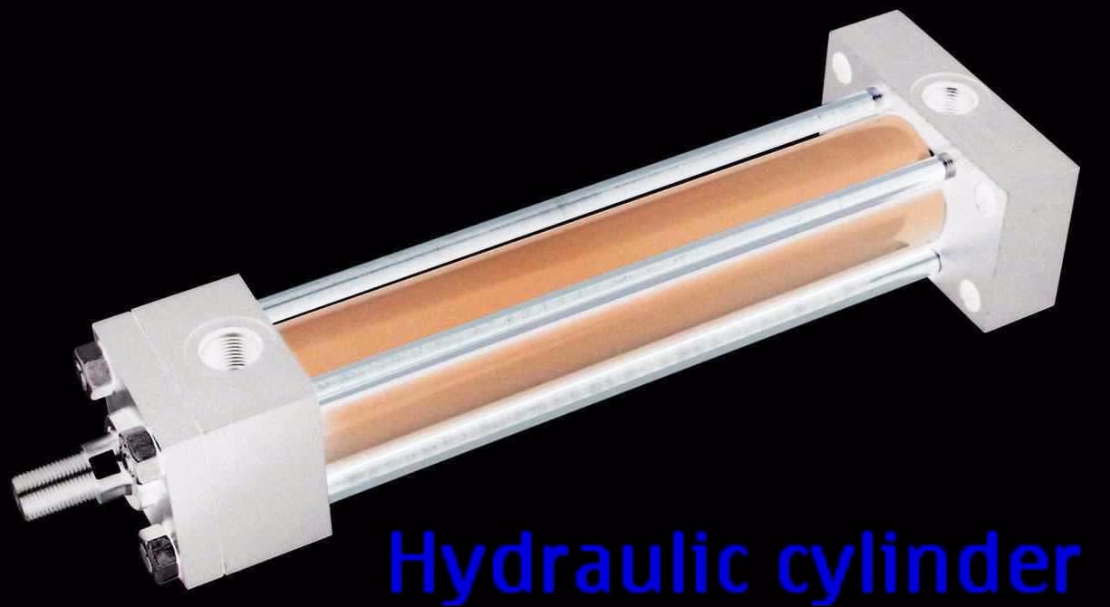
A Hydraulic cylinder


Hydraulic cylinders are known as a linear and mechanical hydraulic motor .
Its a hydraulic actuator that is used at a unidirectional stroke.
The power of hydraulic cylinders resides in the hydraulic fluid.

Type of Styles of hydraulic cylinders

. Hydraulic cylinder are manufactured in two basic styles:

1). The welded body cylinder

: it has no tie rod. The barrel is welded directly to the end cap .

2). The tie rod style:

it is a type that uses a high strength threaded steel rods to hold two end of the cylinder cap to its barrel. The smaller size of tie rod cylinder has four rods while the bigger ones has about 16 to 20 rods.

Components of hydraulic cylinders:


1). The cylinder barrel:

it helps the piston to be connected to the piston rod to enable movement.its closed on each end by the cylinder bottom.

2). The cylinder piston:

which is connected to a piston rod. It has a sliding rings and seals.

3). The piston rod:

that is connected to piston itself but moves up and down.

When we talk about hydraulic pressure pumps. They are the generating part of a machine while the hydraulic cylinder is the actuator or the motor of the machine.


Parts of hydraulic cylinders:


1). The hydraulic cylinder head:

The cylinder head is usually a flanged end connection with a bolt points, which is mounted to the already made flange from pipe or hydraulic hose .

2). The piston:

like we said earlier the piston is connected to the piston rod. Its a short metal that separate two sections of the cylinder internally.

3). Hydraulic cylinder barrel:

is an internally honed thick wall pipe forged in a seamless way.

4). The cylinder cap:

is a part that is bolted to the cylinder barrel. In some cases the barrel are welded to the cap. But for a proper maintenance , the bolting process is the best.

5). The hydraulic piston rod:

is a rolled steel forged with a very hard chrome plate. They are connected directly to the cylinder piston rod and are made to be extended to the cylinder.

6). The cylinder rod gland:

the rod gland is found in the base of the cylinder. It has a seal that prevents the leaking of fluids or oil waste when hydraulic pressure is applied.

Hydraulic Motors


A Hydraulic motors


Hydraulic motors are actuators that mechanically converts the flow of hydraulic pressure into torque and angular rotation through a medium( hydraulic hoses ).Hydraulic motor performs the opposite of the works done by hydraulic pumps.Hydraulic motor is the interchangeable and the rotary mechanised as a hydraulic cylinder.

One of the major different between a hydraulic motor and pumps is that the pump cannot be back driven.

Electric motors , pumps and hydraulic cylinder can be formed together to manufacture a particular hydraulic transmission.

Types of hydraulic motor:


a) Radial piston motors:

it consists of the crankshaft type and multilobe cam ring types. The crankshaft type has a piston and cam pushing inwards while the multilobe type has a cam ring with more lobe and piston rollers pushing outwardly.


b). Gear and vane motors:

it has two gears, the driven gears and the idler gears.

C). Gerotor motors:

is a rotor device with n-1 teeth. These Gerotor are of low - medium speed and medium- high torque.

d). Axial plunger motors:

is used with a gear box. They have a very high rotating capacity.

hydraulic hose nipples


  Hose nipples


Hydraulic hose nipples are hose adapters used on hydraulic hose, pipes and tubings to join or connect to each other.Hydraulic hose nipple is also used with a component like valves, pumps and guages during services usually during hydraulics and fluid transfer.The use of hydraulic hose nipple helps for an easy connection because fittings can be reduced to the lowest form and size easily without too much connections.

Different types of hydraulic hose nipple.

a). JIC male flare threading 37 degree:

the male JIC flare is used to connect a female JIC flare swivel 37 degree.

b). Male pipe NPT threading:

is and adapter to connect to a female Pipe swivel NPT threading.

c). Male O"Ring Boss thread:

is a type of nipple and adapter that has an o" ring seal to it. It could be an adjustable type or non adjustable.

d). JIC Female flare threading 37 degree:

it could be a swivel female or non swivel to adapting to a male pipe nipple JIC 37 degree.

e). NPT Female pipe threading:

these female nipple end is used with a male NPT threading.

f). Female O" Ring Boss thread.

The female thread is used with the Male O" Ring adapter .Hydraulic hose Nipple and Adapters has the above components at different ends and parts.
For example:
A hydraulic hose nipple can consist of 1/4" male JIC to 1/2" male NPT threading as shown in the diagram above.

Ball valves


A Ball valve


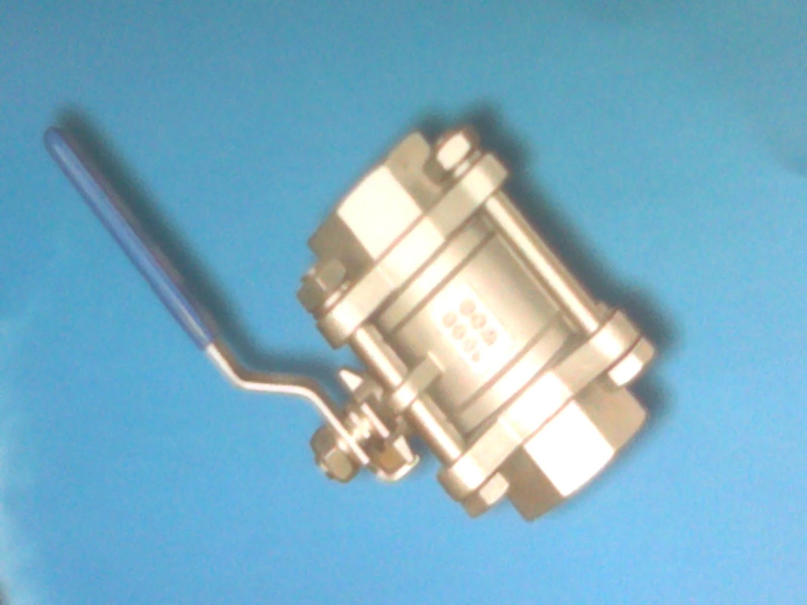
A ball valve is a valve that consists of spherical disc, the handle lever , the threading, the socket welding or the flange.The sperical disc allows the in and outflow of fluids while the handle lever helps the user to determine the position of the sperical disc , telling him or her when to open and when closing.

Ball valves belong to the part family of a quarter turn valve with a plug valve and butterfly valve. They are used on pipeline or at a point where hoses are needed for flexibility.

They are usually used for a long shutoff for years. And a preferable better to be used for this application than Gate valves and globe valves.

Ball valves supports hydraulic pressure up to 1000 bars and with temperature of 482 deg. F. And can be maintained easily. The proper fittings of hydraulic hose with a crimping machine is required to be on the safer side.Ball valves are made of metals,teflon and often chrome plated to enable it lasts longer.

Types of ball valves.

Ball valves are known depending on the body style.
The single body,
the three piece body,
the top entry,
the split body, and the welded.
Other ball valves includes:

a). Full port or full bore ball valve:

it has an enlarge port that has the same size with the pipeline, it reduces friction and is required more where their is always a free flow during pipeline pigging.

b). Reduced port or bore :

is a reduction on the full flow to one pipe size smaller than the pipeline or pipe.

C). A trunnion ball valve:

has an additional anchor at the top or bottom. They are used for a more higher application up to 40bar.

d). Cavity filler ball valve:

its a valve mainly used for the transfer of fluids for human consumption.


 Ball valves sizes Available Includes:

1/4 " ball valves
1/2 " ball valves
3/4  " ball valves
1  " ball valves
2  " ball valves
3 " ball valves
4 " ball valves

please contact us today for purchase

Gate valves


Threaded Gate valve


Gate valve is a valve that is comprise of a sealing surface , a round disc and a rectangular gate or wedge out of liquids or fluids.Gate valve is also called a sluice valve . They are more desirous to use when a straight transfer of fluid and a minimum blocked is required.
They are used not always to be opened and closed regularly but for the purpose of allowing a full flow of fluid and closing them when necessary.Some gate valves are specifically designed to regulate flow and such valves are made to have the ability of cutting through liquids.

Gate valves are used in petroleum industries. Especially for the loading and transfer of thick fluids like bitumen from pipes and hoses.

Characteristics of a Gate Valve


a). A rising stem gate valve:
has the stem attached to the gate of the valve. As the valve is operated the gate and the stem rise and lower together.
b). Non rising stem gate valve:
has a pointer threaded on the upper end of the stem. They are used where vertical space is not required.
C). Gate valve bonnets:
can be a screw-in(the simplest and with a tight seal), bolted(for large and high pressure valves) or union bonnets(for strength, inspection and cleaning) and pressure seal bonnets used for a very high pressure service. They help as a leak proof closure for the body of the valve.

Gate valves are formed in three basic ways:

flanged, threaded and the socket weld.
They are also made or constructed from cast iron,stainless steel, alloy steels,forged steel, gun metal and cast carbon steel.


SIZES OF THREADED GATE VALVES AVAILABLE INCLUDES


1 " threaded gate valves
1-1/2 " threaded gate valves
2  " threaded gate valves
3  " threaded gate valves

Please contact us for purchase today

Valves

 Valves and Components


Valves are technically pipe fittings designed to control, regulates and directs the flow of solids, gases, liquids with the help of pipes and hoses. Such solid particles are fluidized type of solids. Valves are devices that allows the flow of these particles by opening, partially obstructing and total closing passageways.
Valves also can be defined as at device with a hinged flap that obstructs the passage of fluids and other products when pushed close and also allows the flow when pushed open.
valves are used in different companies and industries depending on the type of work they do. Valve is used in Oil and Gas industries, Chemical manufacturing industries,water reticulation industries and maritime industries.

Types of Valves

. Valves are classified into different numerous types and they can also be classified according to the actuator they posses:
Gate valves, Solenoid valves,
Hydraulic valves,
Pneumatic valves,
Motor valves,
Ball valves,

Check valves,
Control valves,
Water valves,
Air valves,
Check valves,
Burkert valves, Denibia valves,
Zoloto valves,
Fisher valves,

Components of a valve

valves comprises of different components depending on the type of valve it is. They includes:
The valve body(outer casing of the valve),

valve ports(the passage of the valve)

valve seat(the internal valve containing a tight seal),

valve stem(transmits motion from handle to disc),

valve disc(movable obstructor in the port),

valve hand wheel or handle(control the valve manually),

valve packing,

valve bonnet(a cover on the valve body) , valve gland nut.
Among the whole component , the valve body and the bonnet seems to be the most important part of a usual valve. The bonnet screws into or bolted to the valve body while the body is the external casing of mostly all valves. The body contains the trim or internal parts of the valve.
Valve bodies are made in different materials. Some are made of bronze, gunmetal, stainless steels, alloy steels, plastics, brass and metals.

Valves are also grouped according to their applications which includes:

a). Alloy 20 valves:
they applied in sulphuric acid plants
b).Duplex valves:
are applied in desalination plants to avoid corrosion in sea waters.
C). Monel valves
used in hydrofluoric acid plants.
d).Hastelloy valves
used in nuclear plants where there is a high increase in temperature.

crowfoot / universal fittings


 Male Npt threaded crowfoot fitting.


Male NPT Universal Crowfoot Coupling is a Chicago coupling with an NPT external threading used to connect two hoses or hose to compressor pump together.Universal Couplings are used together with different connections like weco union. The male NPT is adapted to the female NPT end.
Before using or threading a male Npt crowfoot threading , you must ensure that the female Npt is the same size with the male NPT threading.You must also observe the Rubber seal on the surface of the crowfoot coupling to avoid leakages.

Male Npt Crowfoot couplings are manufactured in with different materials. Which includes:

The stainless steel crowfoot fittings.
The brass crowfoot fittings.
The cast iron crowfoot fittings.


Crowfoot male NPT fittings are threaded to a Compressor machines to be connected to a hose-end crowfoot fitting that is used with an Air or hydraulic hoses depending on the service it provides.

They can also be used during hose crimping operation . The hose must be crimped with a female end NPT threading where the male NPT external threading will be attached. But at a situation whereby the hose is crimped with the use of sleeve directly or making use a double bolt clamps with the hose- end barbed universal coupling, there is no need of using the Male NPT threading since the hose barbed end is already crimped to the hose.

 Crowfoot sizes available includes:

1/4 " crowfoot couplings
3/8" crowfoot couplings
1/2 " crowfoot couplings
 3/4" crowfoot couplings
1 " crowfoot couplings
2 " crowfoot couplings

Please Contact us today for purchase